Bolt: The year of experimentation
After coming back from our first race in the UK, we had a lot of learnings to unpack. Without going into details, the faculty of engineering wrote a piece on our experiences titled “WatSub: When everything that could fall apart ... does fall apart” which sums it up pretty well.

Having gone through an immense effort to built our first submarine, we performed poorly in competition. We saw much more experienced teams outperform us in every way, from craftsmanship and engineering of their submarines, to the bigger budgets they were able to raise, and finally team training and operations. In a way this was by far the biggest motivation: we took a bad first step but an important first step, and now we had a reference frame on which to built on. With that in mind, and the next race in Maryland, US just a year away, we went straight back to work.
Amy was a safe and conservative design: the hull was huge, the drivetrain was a direct drive single two-blade propeller, the control system was fully mechanical, and it left a lot of room for improvement. The Bolt submarine was characterized by a strong desire to experiment with new ideas, and also the need to do so, the trip the UK had left the team in a financially dire state.

Render of Bolt.

Engineering 3D CAD Model of Bolt.
My primary focus for designing Bolt’s hull was minimizing its volume, wet surface, and drag coefficient, in that order. Unlike most submarines, the human powered submarines that we race are flooded (You could argue that its not a submarine but rather an underwater bicycle, well perhaps. I hear back in the day the submarines were pressurized but there were some accidents that led to the change). This means that every unit of volume inside of the submarine translates to mass as per water’s density, increasing your overall inertia.
Making a small submarine is particularly difficult because of the person who must fit inside. The pilot is not just sitting there but also pedalling, so the clearances will vary around your pilot’s measurements and posture, not to mention a wide tolerance stack that includes composite laminates, machined components, and even the thickness of the wetsuit your pilot chose to wear that day. Once the hull is fabricated, the room for adjustments is basically null, so you want to get this right. In order to minimize risk we measured our pilots, generated high fidelity 3D models, built mock-ups of the hull using laser cut plywood cross sections, and did a tolerance study of our last year’s submarine to characterize our achievable in-house fabrication tolerances. And even then we still decided to take a risk and cut it very close.
All of this led to a 33% reduction in volume compared to our last submarine Amy (effectively a 33% reduction in on-board wet mass), while also incorporating bigger hatches onto the hull which improved both safety and repairability (a lot of the times in competition we would service the submarine underwater to save time, through the hatch), and a half-nose cone to improve the frontal crash performance.
Although Bolt’s hull did not include a deep dive into hydrodynamics, we did a first pass study of 2D profiles using Xplane. This simple study led to the selection of NACA 66-021 for the vertical plane profile and S1016 for the horizontal plane profile, these two database hydrofoils were merged through splines optimizing for packaging rather than hydrodynamics. The merging occurred at 4 critical points: the pilot’s head, the pilot’s shoulders (or max. width), and the start and end of the pedals.
Bolt's mould, start of construction.

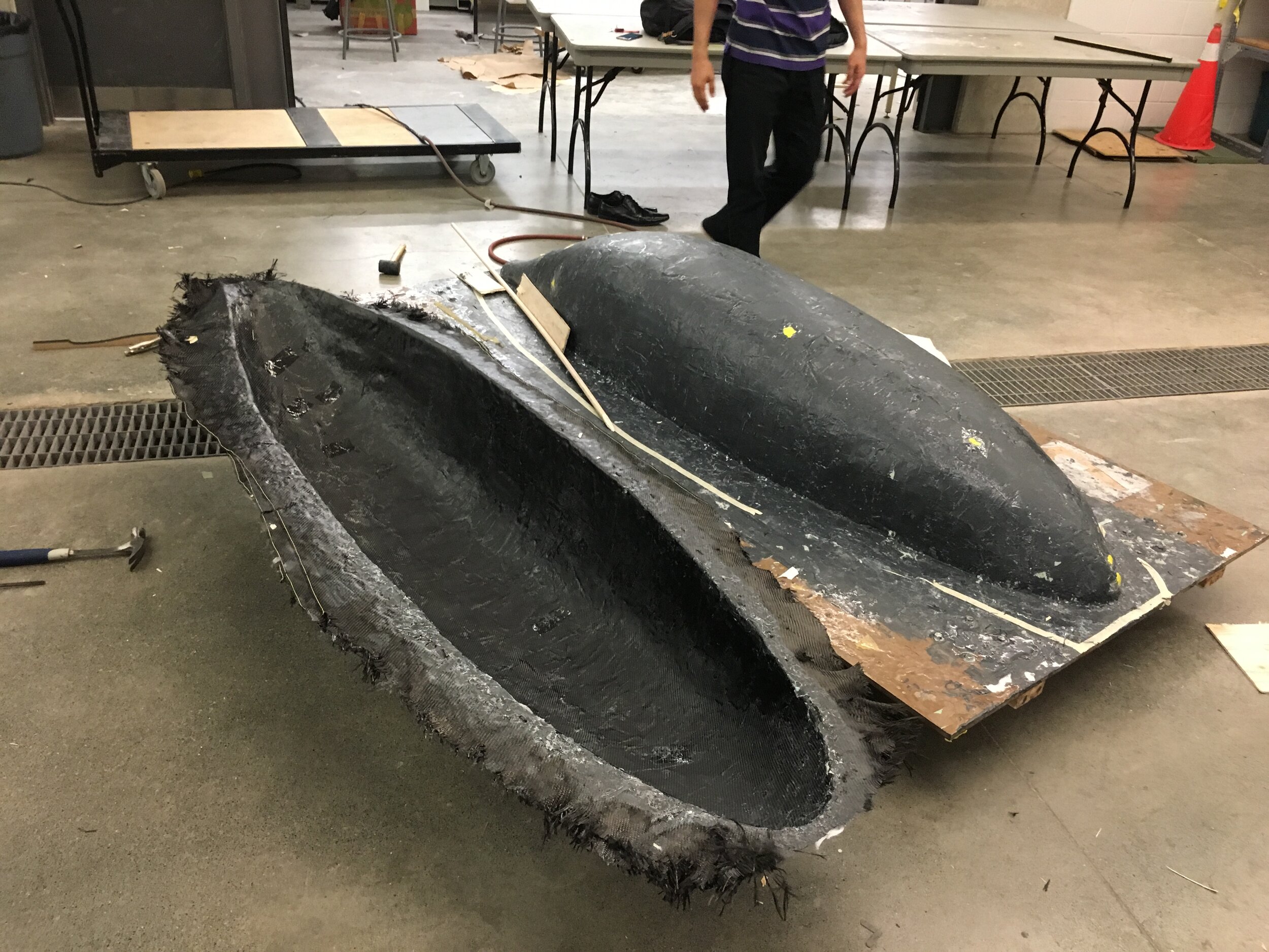
Amy’s mould, Bolt’s mould, and Amy’s hull.
Same as our first submarine, the hull design was done before all other components and its fabrication began very early into the development cycle. To better manage packaging risks, 3D spaces were allocated to each subsystem (propulsion, controls, life support) on CAD ahead of time, each with spatial reduction targets to align the entire team on making a nimble vehicle.
The overall smaller hull size of Bolt can be appreciated in the picture above, where a rough Bolt mould sits next to Amy’s hull and Amy’s mould.
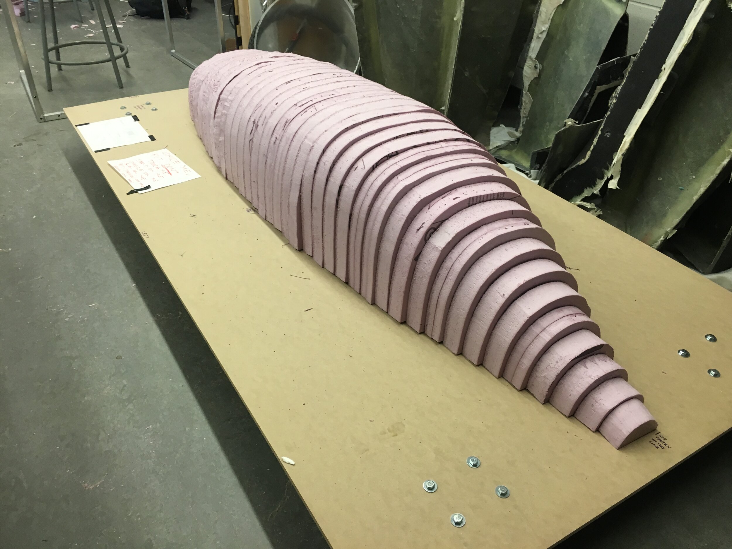
Having used most of the team’s budget last year on Amy and taking the team all the way to Europe, Bolt’s budget was limited. We knew from last year’s submarine that most of the hull’s cost comes from the tooling (moulds) and not so much from the composites material, with this in mind I designed the tooling in a way that it would be 100% done in-house and out of cheap materials. We generated 46 cross sections of the hull, made paper templates, and cut them out of insulating polyurethane foam. The cross sections were stacked on top of an MDF board, using a triangle datum feature and a dowel running across to position the cross sections accurately. The board would act as the structure of the mould, plus be sealed to hold vacuum.
We spent a total of $300 making the mould, down from last year’s $2000.

Foam mould after sanding.
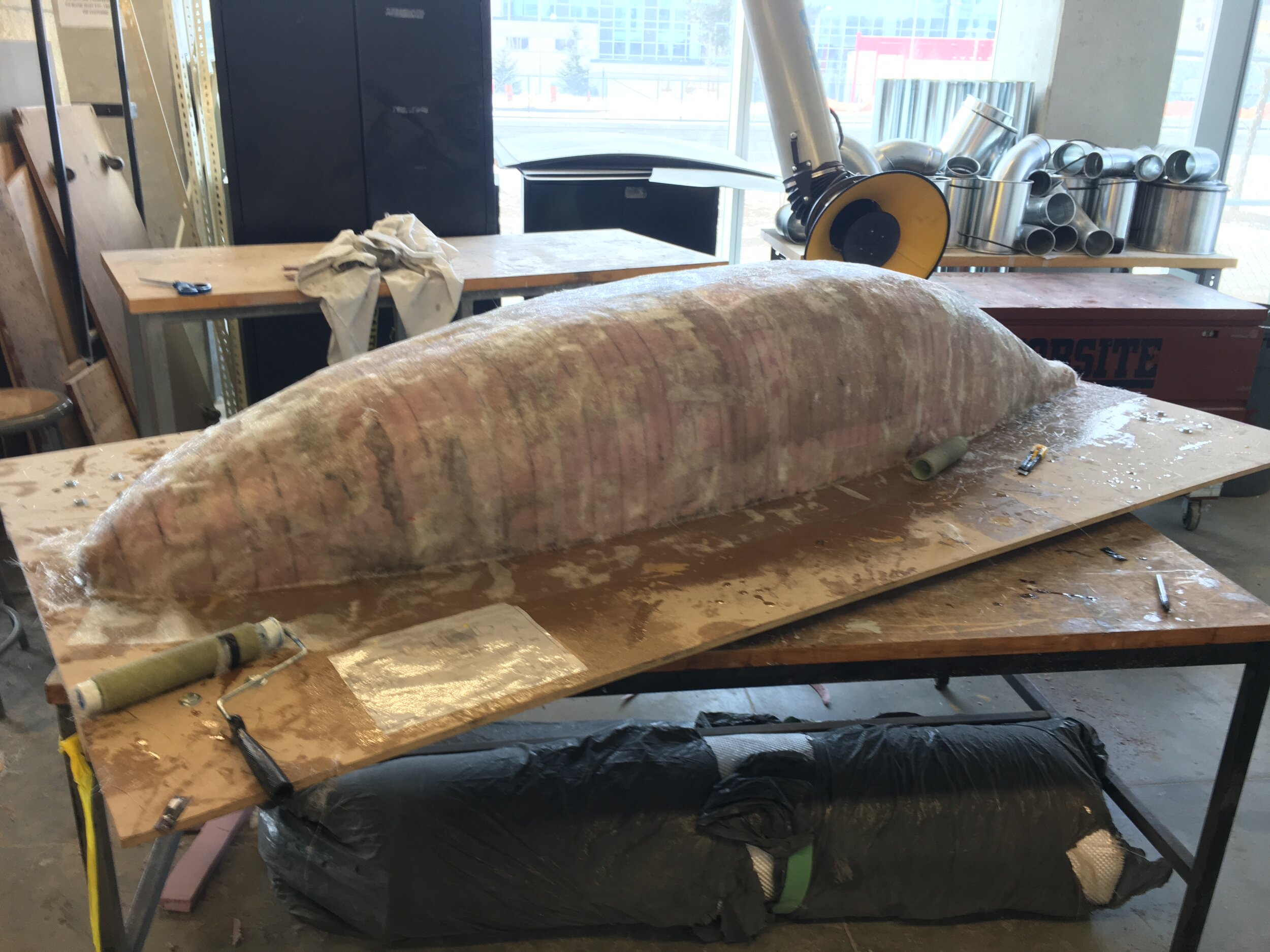
Foam mould after fibre glass sealing.

Foam mould after filling and priming.
After stacking the foam cross-sections and glueing them together, we sanded them to a continuous curvature. To maximize the accuracy of the mould curvature to that of CAD, we used as many cross-sections as possible, and as thin of foam boards as available.
We sealed the foam with fibre glass chop strand mat and epoxy resin (polyester resin would have dissolved the foam as its MEKP solver / hardener has that effect on polyurethane, so the more expensive epoxy was required). After that we sanded some more, body filled, and lastly applied a polyester based primer coat before we started wet sanding and polishing.
You may have noticed I refer to this as a mould and not a plug, and that’s correct. The plan was to use a male mould to lay up our hull. This is less than ideal in terms of surface finish, core reinforcements, part quality, and demoulding, but at the time it appeared like the best alternative. Remember the constrains: competition only months away, not a lot of money in the bank, and not a lot of expertise in composite manufacturing (this was only our 2nd submarine).

Male mould layup in progress.
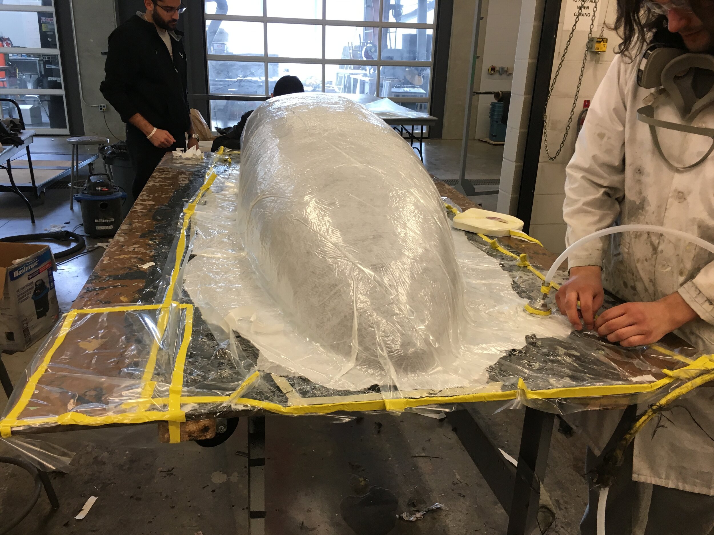
Vacuum assisted wet layup.
First half demoulding.
The final schedule of the hull was a 4 ply, 250 gsm, twill carbon fibre construction with an epoxy resin system, with a calculated 1.5mm wall thickness. The material was again selected around economics, the submarine hull is optimized around stiffness rather than strength, this weave of carbon fibre is widely available in North America, and we had conducted previous material characterization experiments on it so we were comfortable designing and building with it.
In contrast with Amy’s hull fabrication, we used a vacuum assisted wet layup process rather than an infusion, particularly to reduce consumables and also because of the geometry of the mould. We also used a waxed peel-ply to prime the final part for the painting process.

Hatches marked & trimmed.

Foam core hull reinforcements.

Foam core hatch reinforcements.
I believe in small incremental improvements that compound over time, and as I complaint about Amy’s poorly trimmed hatches, we trimmed Bolt’s hatches using datum points and even rounded the corners. All around better craftsmanship, it improved the finish of the submarine.
Now, one of the many disadvantages of doing a layup on a male mould is that you cannot add core reinforcements (for stiffness) as they would protrude on your exterior surface, leading to disrupted flow and poor aesthetics. This reason alone is enough to avoid using a male mould if you do require core in your structures. Our solution was to do multiple lay-ups on the hull and hatches to add core and more layers of carbon. These subsequent operations on the hull were less than ideal because it was not possible to pull any vacuum (effectively a wet layup). We were able to pull vacuum on the hatch reinforcement but to our surprise (obvious in hindsight) it led to the hatch warping and not matching the curvature of the hull once cured.

Hull on jig for marriage.

Hull going through the paint process.
The marriage of the two hull halves was also done through a wet layup without vacuum. Unlike Amy, Bolt’s hull had no interior flanges that could be used for bonding (another setback of the male mould) so we just put carbon on top and got as good of a surface as we could get by curing it with peel ply over it (this worked surprisingly well).
Another small incremental improvement that year was the paint job, you would not believe how many times I had to tape that curve to get it just right. We also invested on a spray air gun so we could use higher quality paints compared to Amy’s spray can paints off Home Depot.

Forming the sand mould.

Melting the foam positive.

Casted part off mould.
While talking about Amy’s development I said that part of going to an engineering competition is showing off, here’s an example of this. I was just coming back from an internship at a car company where I got to design sand casted parts and thought we should attempt to do the same. The idea fit well within the project’s context: we had no money for CNC’d parts so if we wanted geometric freedom beyond what we could mill ourselves, we would have to be creative.
I designed a bracket that would connect the propulsion system onto the hull, and we recreated it using foam. We then used the foam as a negative and put ‘green’ sand around it and packed it tight (in reality we used a combination of cat litter and playground sand). We then got all of our scrap aluminum together, and the engineering department was kind enough to entertain our project and let us use their oven. The above is the part off the mould, it was surprisingly good / low porosity, and was usable after machining the open boundary surfaces.

Plaster mould for casted fins.

3D printed mould for fibre glass fins.
Another area for improvement coming from Amy was the control surface fins. During competition we would break a lot of fins. Think about it: the fins are slender structures that protrude well beyond the hull in search of a clean stream of water flow. They are also the impact point when you crash onto the pool’s floor or walls.
Amy’s fins were complicated carbon fibre surfaces with a sheet metal bracket and a shaft, too many parts to break, too hard to repair during competition. So we embarked on a brainstorming phase to find a better design. We tried 3D printing moulds that we could use for quick fibre glass layups (3D printed moulds meant cheap tools, such that we could have a lot of them and increase our production capabilities), and also tried urethane casting them. The first iteration of both ideas was poor.

Machined fin mould.
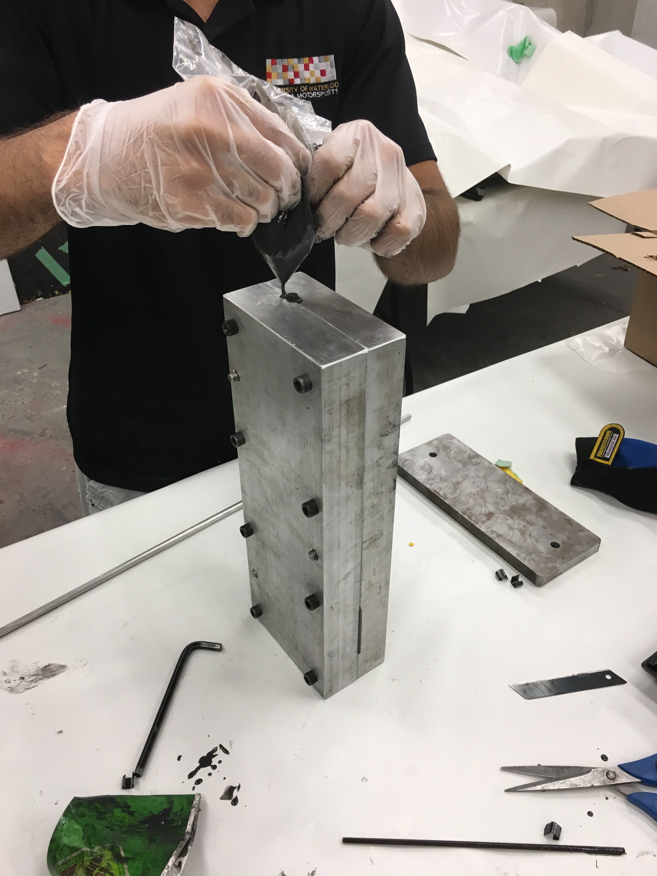
Fin pour.
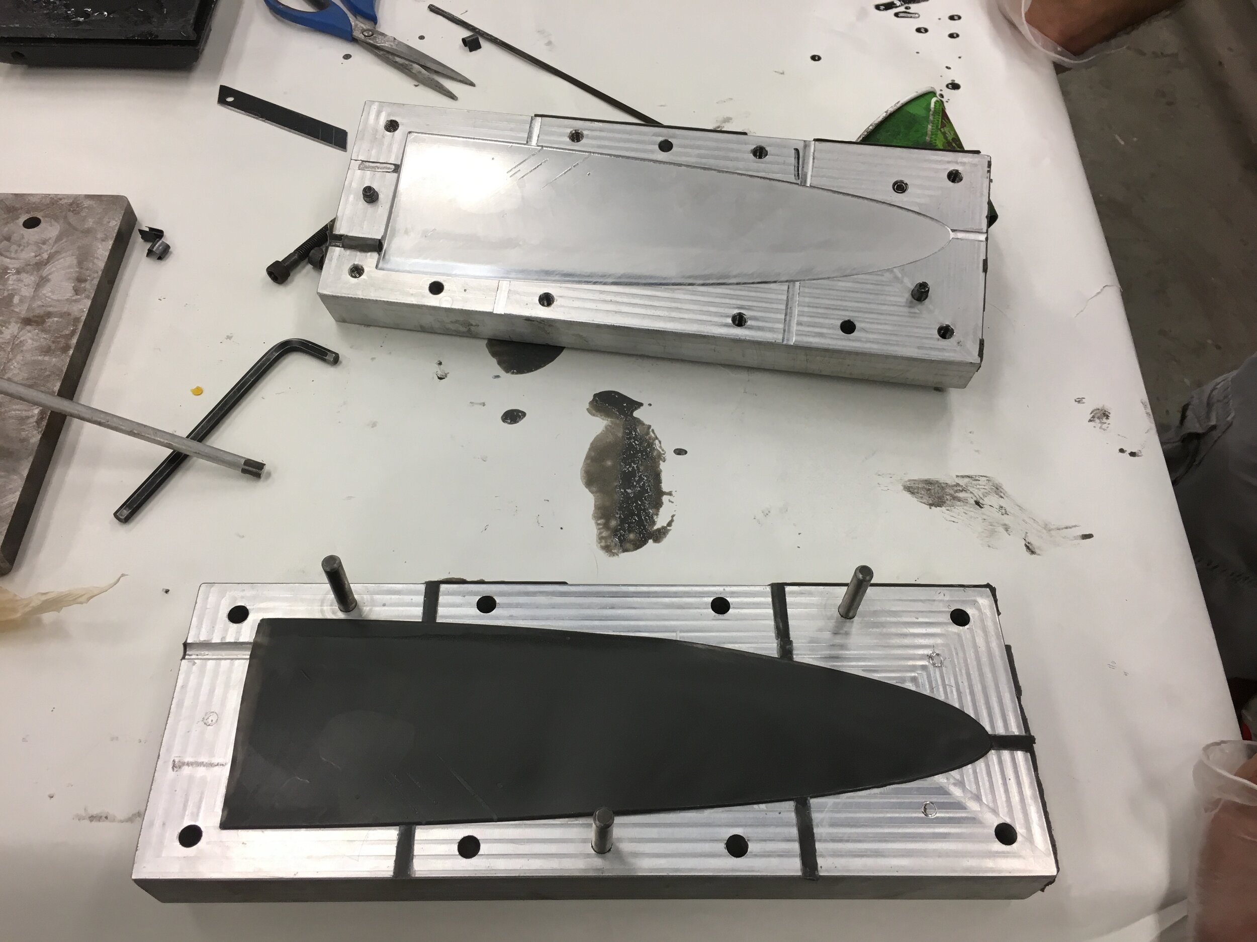
Cured casted fin in mould.
We decided to invest in the fin casting process, going from plaster tools that kept crumbling, onto heavier duty aluminum tools which we designed ourselves. The mould would allow us to insert a knurled shaft that would then bond to the urethane fin inside the mould. The resin would cure in as little as 12 minutes and the failure mode for most crashing was the urethane part getting destroyed and not the shaft, so overall this design was great. We could then bring the robust tool and a bunch of resin to competition and cast on site as needed.

Casting of the safety buoy.

SLA 3D printed safety strobe bracket.

SLS 3D printed nylon propeller hub.
A few other experiments included the casting of the safety buoy, which meant we could move away from making buoys out of foam panels. This gave us more geometric freedom, a greater variety of densities, better bonding to the hull, and some structural opportunities.
3D printed parts also became widely used throughout the submarine, including an SLA PLA bracket for the safety strobe (a shiny light you can see from the surface to locate the submarine underwater) and a SLS nylon propeller hub assembly (here you can also see the contra-rotating propeller design, which required a pretty clever double shaft drive train: a solid shaft inside a hollow shaft).

Thermoforming window mould.

Thermoformed PETG window.
Yet another improvement was the fabrication of a window mould to thermoform a window out of 0.10” PETG sheets. For Amy we used the mould and heat guns to try to thermoform a plastic sheet, but with a dedicated window mould meant that we could use proper thermoforming equipment, leading to much better results (a more structural window, with less optical distortion).

CNC’d propeller blades.

Welded sheet metal control system structures.

Controls handle.
With Bolt we also extended our metal fabrication capabilities beyond the mill and a band saw, and ventured into welding and sheet metal forming to create the control system structures. Continuing the trend of improved metal fabrication, we got better at fixturing the propeller blades for CNC milling, plus went to polish the aluminum blades for better performance.
Bolt’s control system was an upgrade from Amy’s fully mechanical system (it used wires, similar to that of a cheap bicycle), with the team coming up with a hydraulics design which made use of the limited space more efficiently.
That summer we road-tripped to to Naval Surface Warfare Centre in Maryland, US to race. We brought a bigger diving team and a better submarine, but still performed relatively bad. Rather than blaming the team’s lack of experience, this was a management issue: a diminishing budget and tight timeline let to too many corners being cut. But overall the team was improving and we had a clear grasp of the areas we wanted to improve in, so we adjusted accordingly and got to work on our 3rd generation submarine.

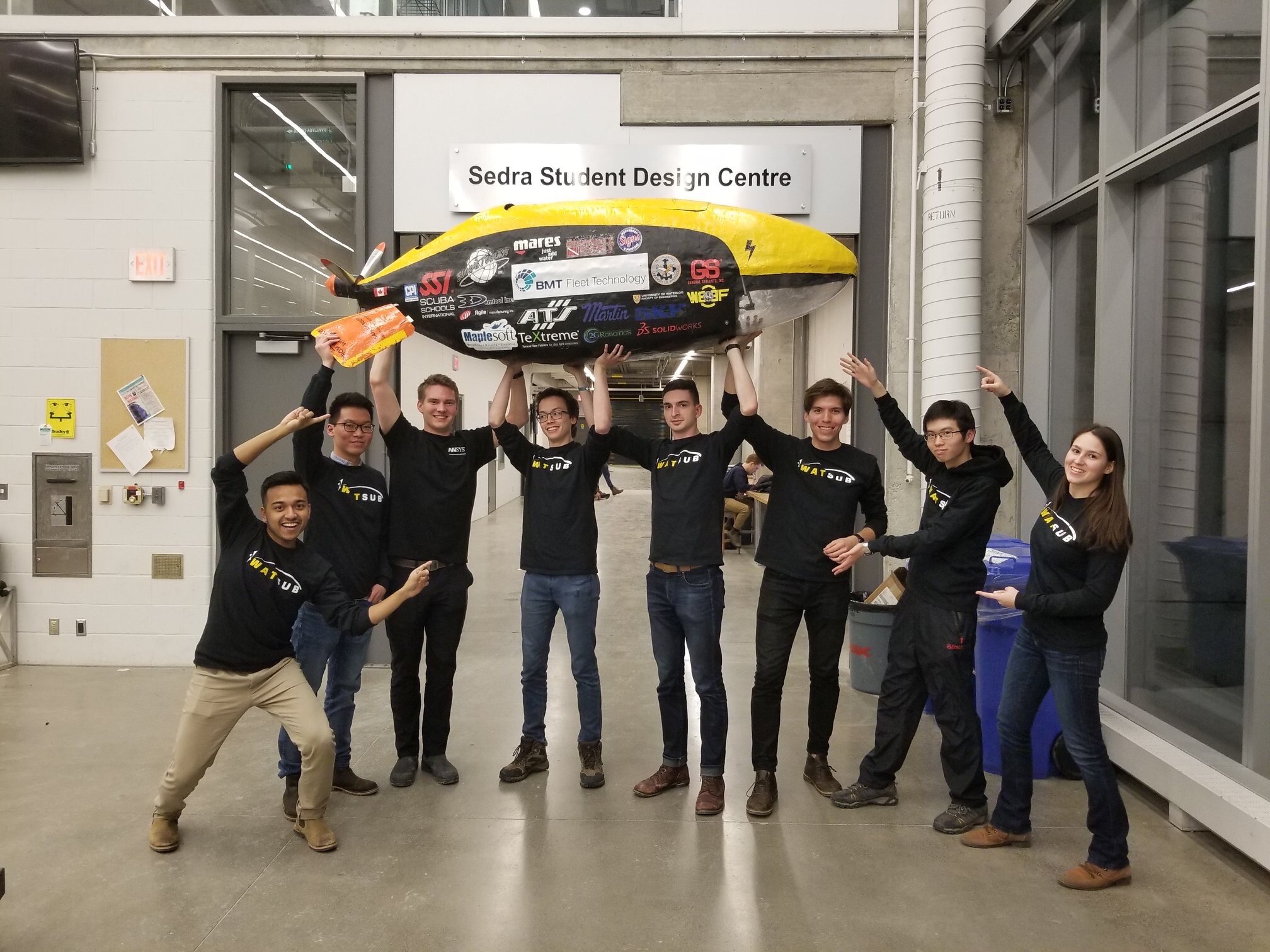
Bolt in its final form.
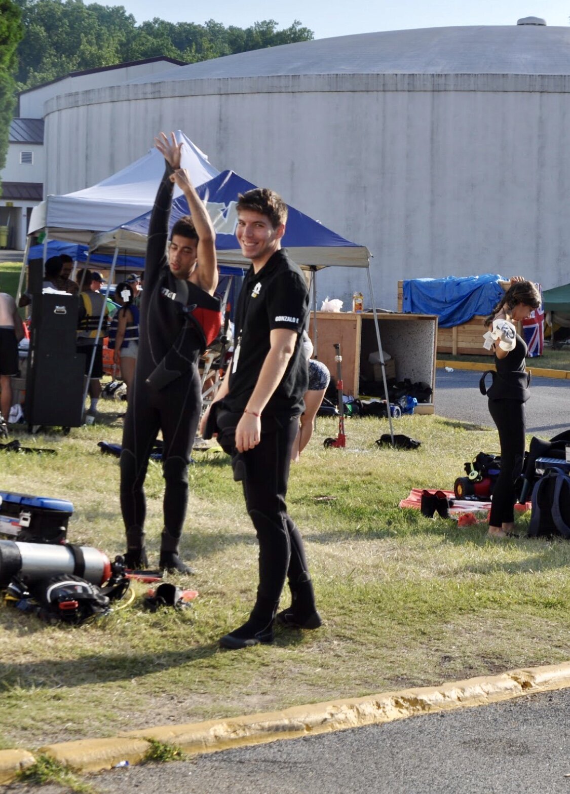
The team and I preparing for a dive in Maryland.